top of page

Projects

The design process began with initial mission requirements: target range, cruise speed, flight altitude, and an estimated total weight. Using these parameters, we conducted an aerodynamic performance analysis to guide the sizing of the drone.

To evaluate efficiency across different wing loading conditions, the drag equation was reformulated to express thrust loading as a function of wing loading. This allowed us to generate a thrust-to-weight vs wing-loading curve. The curve reveals how the required thrust, drag, varies with wing area: at low wing loading, induced drag dominates and therefore total drag is high; as wing loading increases, induced drag decreases while parasitic drag begins to rise. The optimal wing loading is found at the minimum point on the curve, where total drag (and thus thrust requirement) is lowest.

This analysis delivers an initial optimal wing area given the estimated weight and initial chosen characteristics. With this value a cyclical and iterative process can occur. Different characteristics of the drone can be updated to show the performance of different geometries, dimensions and profiles of the drone. These characteristics can be the aspect ratio, taper ratio, swept back angle, dihedral angle, parasitic drag (form drag, interference drag, skin friction drag) for different materials, finishes, NACA airfoils and fuselage-wing geometry. 

Next, an electronics and power analysis is incorporated into the iterative process. This step is crucial because the power needed to achieve the required range and thrust depends directly on the total drag. As drag increases, more energy is required, which in turn affects the size and weight of the battery. This updated battery weight contributes to the total mass of the drone, which must be fed back into the wing loading and thrust loading analysis. The process is repeated, updating aerodynamic, structural, and electrical parameters, until the assumed initial weight used in the performance analysis aligns with the final calculated weight, ensuring the design can meet the desired range and flight conditions.

Once an optimal wing loading vs thrust loading condition has been found, which not only takes into account aerodynamic performance but also manufacturing capabilities and cost, the initial prototype drone can be designed. 

One of the most critical aspects of the drone's design was determining the optimal placement of the vertical lift propellers. Achieving sufficient pitch control authority through thrust vectoring alone required a detailed stability analysis. To enable this, the wings were swept back significantly, which increased the longitudinal distance, or moment arm, between the front and rear vertical propellers relative to the drone’s center of gravity. This configuration ensured adequate pitch control during all phases of flight. Nonetheless it also decreased the perpendicular airflow velocity with respect to the leading edge, this decreases lift. Therefore the resulting changes in aerodynamic behavior were fed back into the performance analysis, and additional iterations were carried out to refine the drone’s final geometry and ensure it met the targeted range requirements.

Below are two reference graphs from General Aviation Aircraft Design: Applied Methods and Procedures by Snorri Gudmundsson, which were used to support the analysis above. The thrust-to-weight graph on the left served as a guideline for comparing various aerodynamic characteristics of the drone. The graph on the right, illustrating the relationship between aspect ratio, taper ratio, and drag factor, provided key data for the iterative design calculations.

Embedded Lift: Novel VTOL Approach

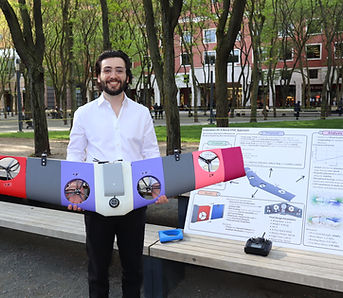
Invented a modular, long-range VTOL drone platform capable of vertical takeoff/landing, and hovering. Unlike conventional approaches, the design tests the feasibility and efficiency of integrating the vertical lift propellers inside the wing structure.

The conveyor belt system - excavation and deployment system - was designed to pivot around a point on the front of the robot, this allowed us to store the conveyor belt to meet the size requirements and then deploy it with a large range of motion and volume collection potential. The conveyor belt system was designed to be functional in both directions, which meant that it had buckets facing both directions, when spun anti-clockwise, the conveyor belt would digg material and transport it to the storage location, when spun clockwise, the conveyor belt would transport the material out of the storage location into the intended area in the arena. 

On the other hand, a scissor lift mechanic was chosen due to the high loads that the collection-storage-deployment bin would encounter when fully loaded. This still allowed us to store the system tightly to meet the initial size constraints but then provided a large range of motion and force that could be used to achieve the system's three objectives. When the bin was used for storage, the linear actuators were completely retracted and the bin had a slight downward slope that would hold the material carried by the conveyor belt. When translating the linear would either stay in place or slightly raise to shift the weight of the material and balance the robot, and when deploying, the linear actuators would fully extend and let the regolith fall onto the conveyor belt system which would then carry the material to the intended location in the arena. 

NASA Robotic Mining Competition 2023-2024

Design and construct a rover for lunar exploration, focused on transporting lunar regolith to construct berms for habitat and protection. 

In addition to redesigning the excavation mechanism, we had to rethink the translation mechanism. As we learned from last year, linear actuators are extremely useful, but they take up a lot of space and are considerably heavy, therefore for this year we implemented a pivot point system, this allowed us to have a much larger range of motion, while also providing a much lower count of failure points. 

Nonetheless in order for the chassis to withstand such a high torque, it had to be reinvented. The objective was to distribute the concentrated moment as efficiently as possible through the entire chasis. In order to do that, we needed to decrease any loose connections, between the beams, that could wear and tear over time from the repetitive loading and potentially lead to failure, while also increasing the strength of the beam components that made up the chassis. In order to do so we decided to utilize aluminum box tube as the structural frame, for their high strength-weight ratio, and most importantly 3D printed closed fit connections between beams, that would hold tight each component an eliminate any type of insecure connections, while also providing us the capability of disassembling if needed, something welding did not provide.

NASA Robotic Mining Competition 2022-2023

Design and construct a rover for lunar exploration focused on the collection and storage of lunar regolith for water and organic matter analysis.

Soft Robotics

Design a soft robotic finger with vision based proprioception for 3D shape reconstruction.

1 Ajuste.png

NASA Robotic Mining Competition 2021-2022

Design and construct a rover for lunar exploration, focused on the collection and storage of lunar regolith.  

bottom of page